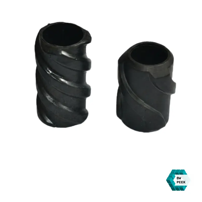
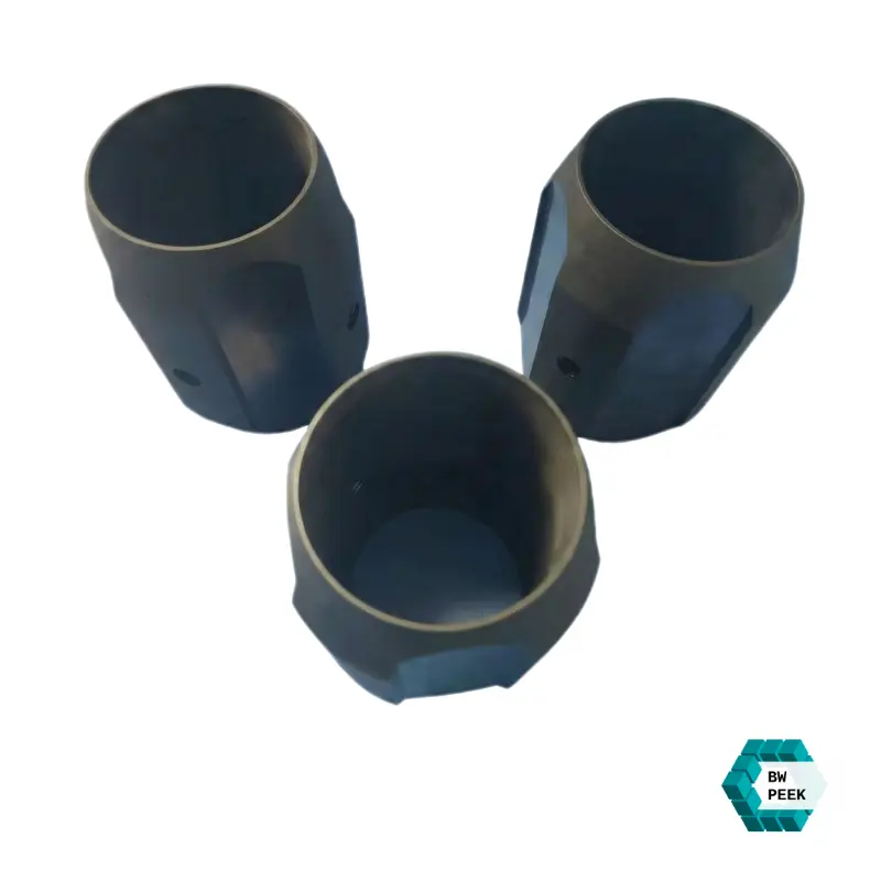
| Tubing/Casing Size (in) | Body ID (mm) | Max Rib OD (mm) | Total Length (mm) | Target Borehole Size (in) | Typical Application |
| 2-3/8" | 61.5 | 95 - 105 | 150 - 200 | 4-1/8" - 4-1/2" | High-temp HPHT Tubing |
| 2-7/8" | 74.5 | 110 - 120 | 180 - 220 | 5" - 6" | Velocity Strings / Slanted Wells |
| 3-1/2" | 90.5 | 125 - 140 | 200 - 250 | 6" - 6-3/4" | Deep Gas Well Completion |
| 4-1/2" | 116 | 145 - 165 | 250 - 300 | 6-3/4" - 7-7/8" | Horizontal Section Liners |
| 5-1/2" | 141.5 | 190 - 210 | 250 - 350 | 8-1/2" - 9-1/2" | ERD (Extended Reach) Casing |
| 7" | 180 | 205 - 240 | 300 - 400 | 8-1/2" - 12-1/4" | Intermediate Casing Strings |
| 9-5/8" | 247.5 | 290 - 310 | 350 - 450 | 12-1/4" | Major Hole Stabilization |
When exposed to wellbore conditions above 195°C with high H2S content, conventional composite centralisers show 40% rib wear after deployment to 4000 metres due to the action of friction causing heat and chemical degradation.
Our solution:
Installing PEEK Centralizer (especially the high performance carbon fibre reinforced ones) is not a trivial process, and cannot be categorised as a simple "sliding" action.
Owing to the exceptionally low coefficient of friction inherent to PEEK (approximately 0.12), if incorrectly installed it may suffer a downhill slip, analogous to that of an eel, thus denying its ability to maintain centralisation.
To ensure optimum performance from this equipment with a high value, the following "Hardcore Installation Guide" is recommended:
Procedure: Before the well entry the outer diameter of the casing or tubing should be measured against the inner diameter of the PEEK centraliser.
Recommendation: Since the PEEK Centralizer are created through CNC precision machining with tolerances that are set at +-0.05 mm, if there are pronounced burrs or substantial paint layers on the tubing, they must be removed before tube installation. It is important to note that even a 1mm deviation can compromise downhole stability.
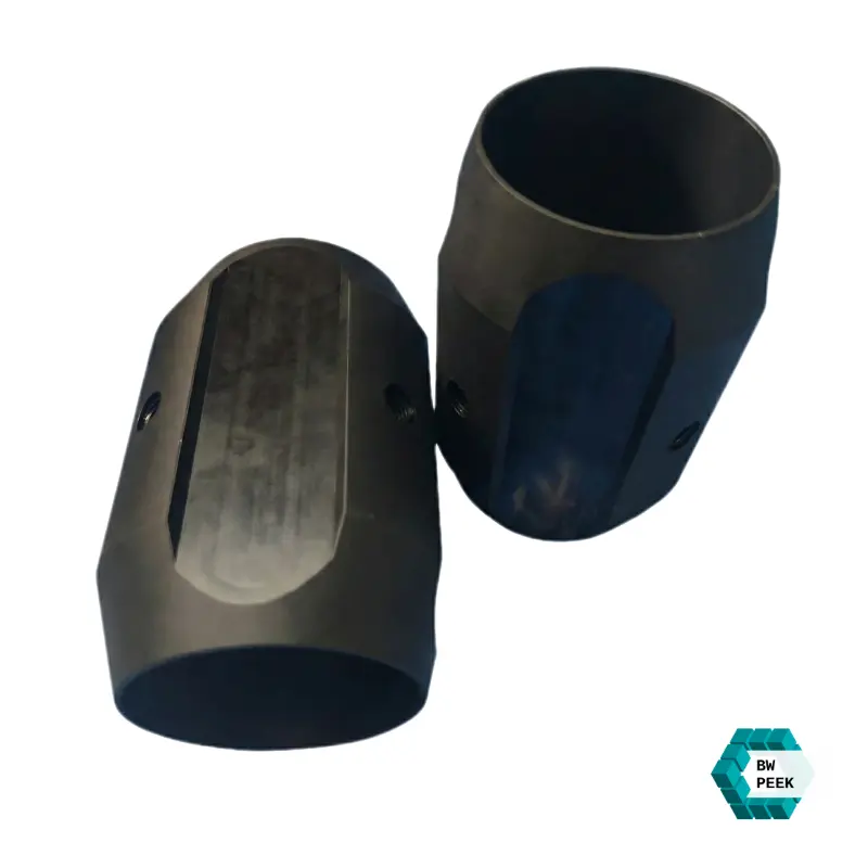
Operation :The PEEK Centralizer comprises of a sliding configuration and requires the use of stop collars.
Core Parameters:
Single Stop Collar Installation :
Mount the stop collar below the centraliser, in which it can be free to rotate at the top (suitable for rotary running in wells with large displacement).
Dual Stop Collar Installation:
Mount one above and one below in order to "lock" the centraliser within a fixed range.
Operation:Fit the stop collars to the tubular string using the hexagon socket bolts supplied.
Data The fastening bolts for the stop collars must be tightened using a calibrated torque wrench. The torque values are usually in the range of 80 to 120 Nm depending on the bolt specifications.
Warning: By virtue of PEEK's low-friction properties, it is possible for the centraliser to be 'freed' in the insertion process if insufficient attention is given to the tightening of the thrust rings, especially in the event of a tapered formation. Such disengagement not only does not admit of proper centralisation but is liable to cause a pipe sticking.
Procedures Installation should be based on the spacing schedule obtained from design software (e.g., CentraDesign).
Field Parameters: While performing horizontal sections, it is generally recommended to instal 1 unit for every one to 2 pipe strings.
Summary: Expenditure for proper installation should not be minimised for marginal weight saving. The cost of an additional PEEK Centralizer is minority to the cost of the failed run or the abandonment of the entire well.
| Feature / Property | Carbon Steel Centralizer | Reinforced Nylon (PA66) | PEEK Centralizer |
| Max. Operating Temp (Continuous) | 300℃+ | 110℃- 130℃ | 260℃ (Continuous) / 315℃(Peek) |
| Coefficient of Friction (Wet) | 0.35-0.50 | 0.20-0.25 | 0.12-0.15 (Up to 75% Reduction) |
| Compressive Strength | >400MPa | 60-80MPa | 160-190 MPa(High Rigidity) |
| Water Absorption (24h) | 0% | 1.2%-1.5% (Risk of Swelling) | <0.1% (Zero Dimensional Change) |
| H2S / CO2 Resistance | Poor (High Risk of Hydrogen Embrittlement) | Moderate (Polymers may degrade) | Exceptional (Total Chemical Inertness) |
| Casing Protection | High Wear (Damages 13Cr/Chrome) | Non-damaging | Protective (Low-wear, Self-lubricating) |
| Running Success Rate | Baseline | Risk of Melting/Deformation | 100% (Proven in ERD & HPHT Wells) |
| Service Life (High Acid Env) | <2 Years | 3-5 Years | 10+ Years (Ultra-Long Durability) |
To make sure you get genuine value on our official website, below you can find the parameters of our factory random sampling tests: